آزمایشگاه بین المللی چمران
مرکز آموزش مهارت های پیشرفته - آموزش در مسیر اشتغالآزمایشگاه بین المللی چمران
مرکز آموزش مهارت های پیشرفته - آموزش در مسیر اشتغالExperiment 04 - advance Laser Lab
Experiment
- Set-Up
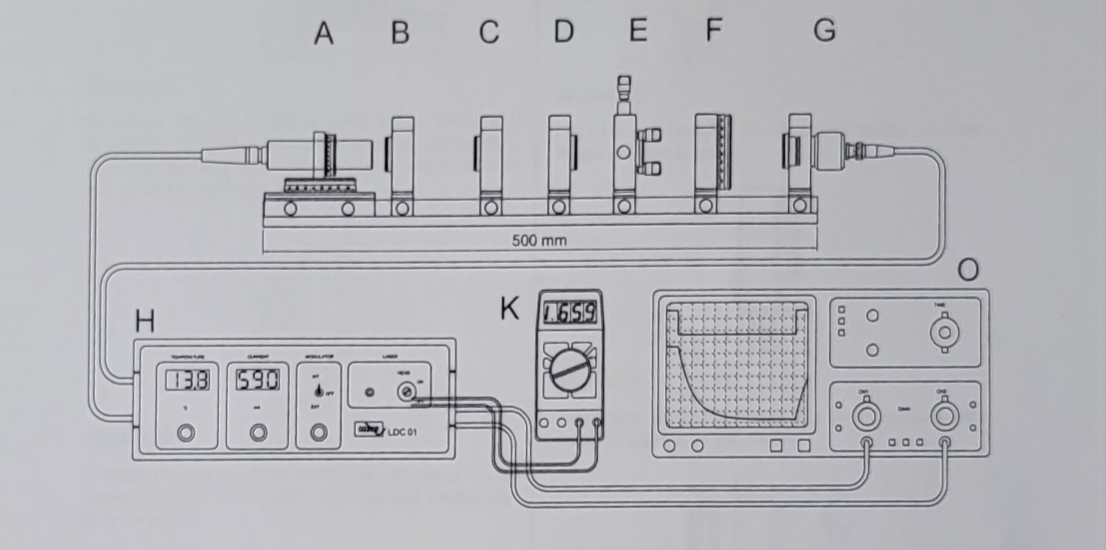
- Description of Module
- Module A
- Module B
- Module C
- Module D
- Module E
- Module F
- Module G
- Module
- Spatial Beam Distribution
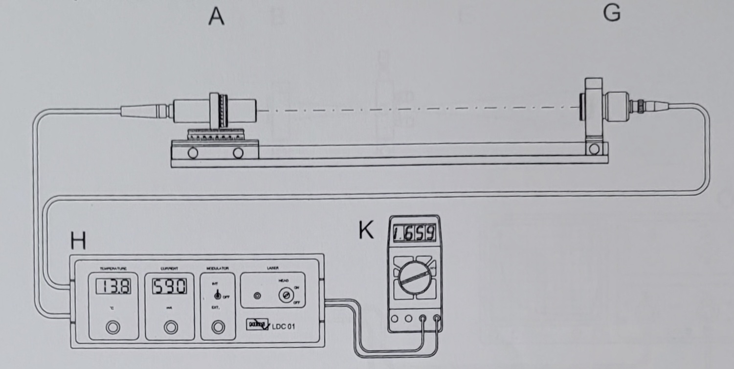
With the above set-up the Beam geometry of the laser diode will be measured. The Module A (Laser diode with tow axes rotational stage) and the photo detector (Module G) are used. In front of the detector a pinhole mounted in a click mount is inserted into the mounting plate.
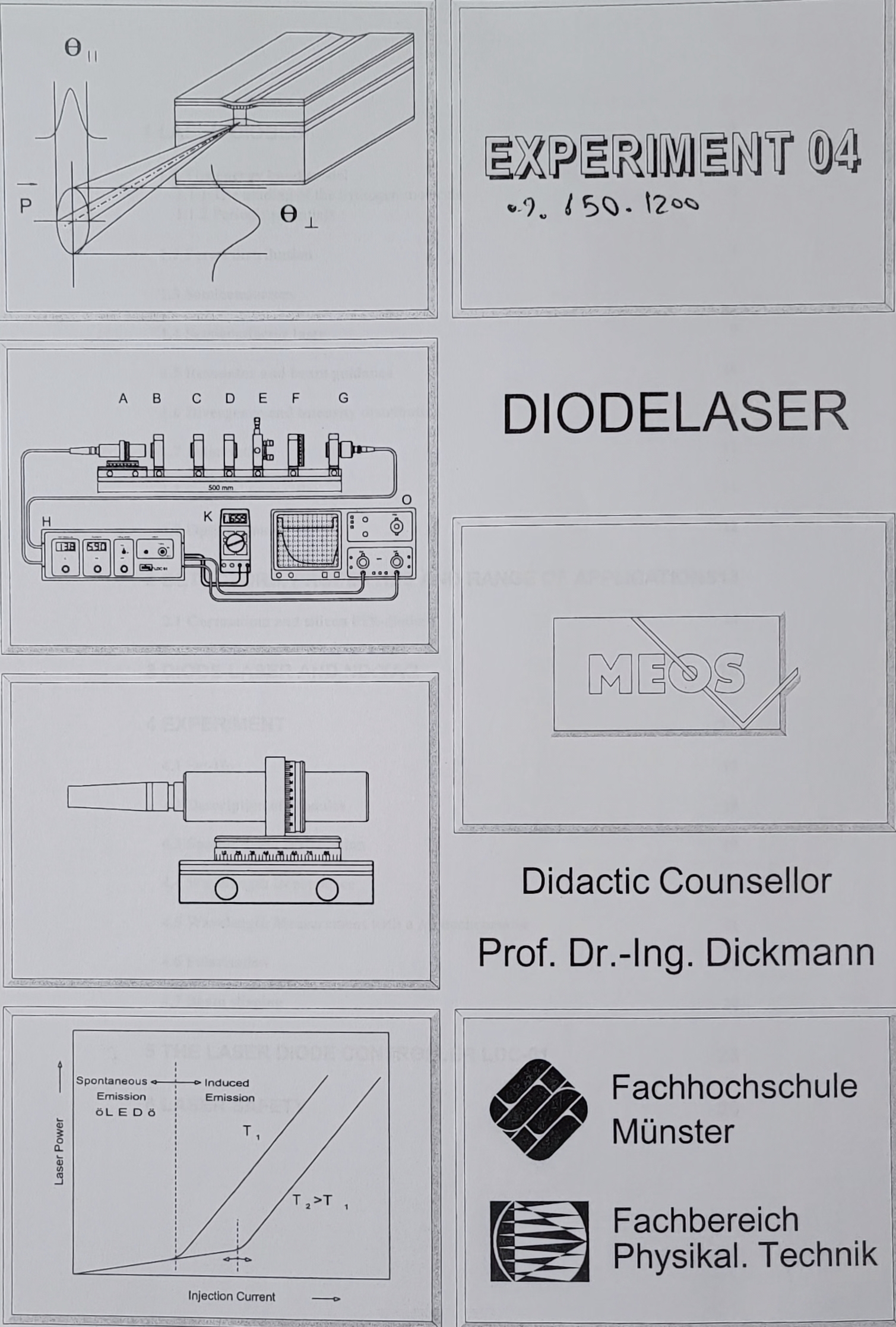
The laser diode can be turned around its optical axis as well perpendicular to it. Turning the diode around its optical axis is provided to align the diodes elliptical beam cross section with respect to the plane of the other rotational stage. By rotating this stage the angle resolved intensity distribution of the laser diode emission is been measured.
The photo detector is connected to the BNC socket at the rear of the control unit the section "INPUTS" marked with "PHOTODIODE". The BNC outlet marked "PHOTODIODE" within the section "OUTPUTS" is connected to the digital voltmeter. The voltmeter is switched to DCV.
One has to make sure, that the detector will not be saturated by the laser light. A pinhole is used to reduce the sensitive area of the detector for better angle resolution as well for avoiding the saturation of the detector.
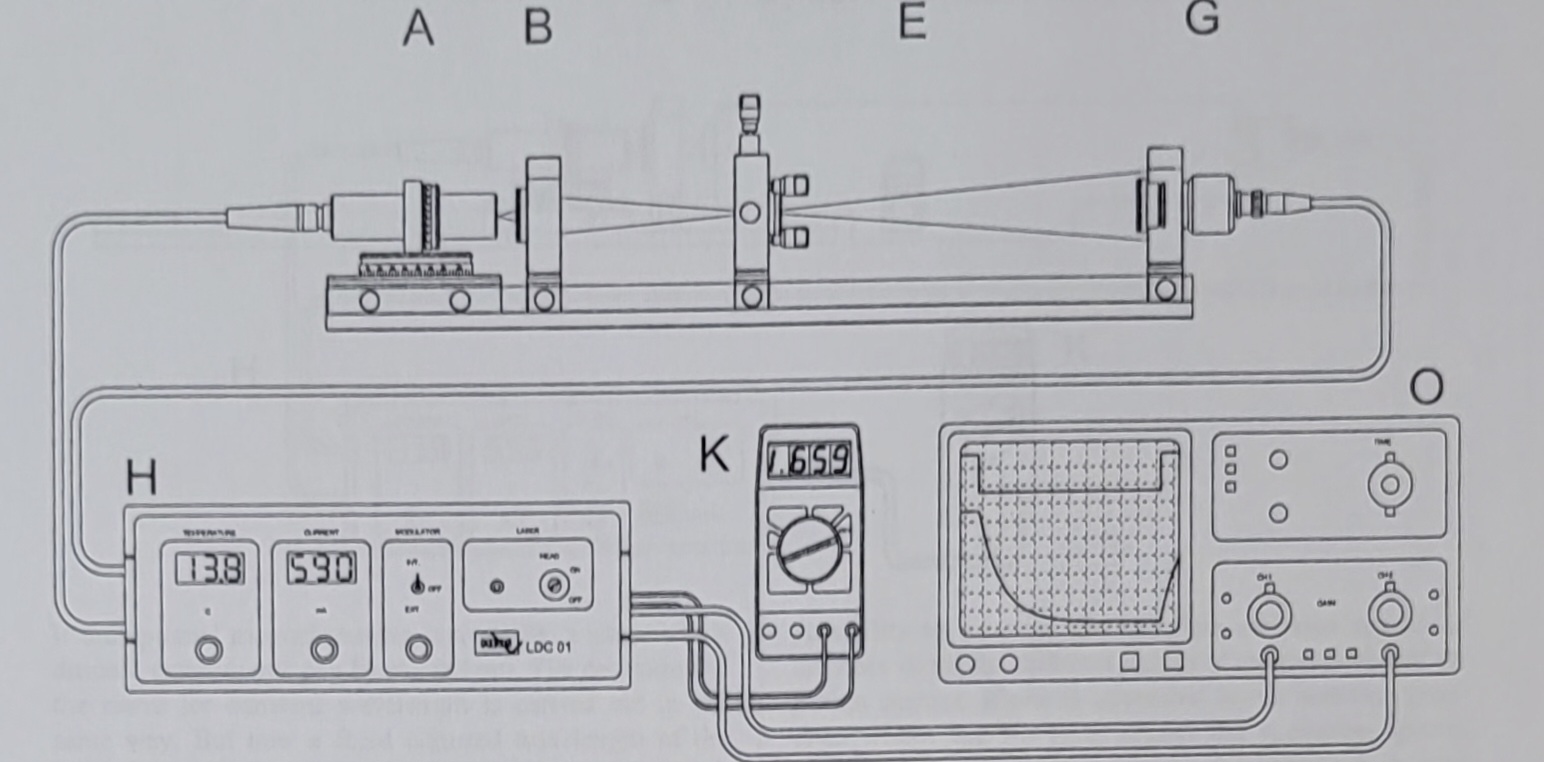
Of course the detector output of the control unit can also be connected to on oscilloscope. In this case the modulator of the control unit can be activated for producing AC signal.
Within the same set-up the dependence of the laser power versus injection current and temperature can be measured.
In addition the behaviour of the laser diode is measured when it is modulated either by the internal modulator (rectangular amplitude, switch MODULATOR on the front panel is set to the INT. position) or by an external modulator. In the latter case the signal of the modulator is fed into the BNC socket within the section " INPUT" marked as "EXT". MOD." and the switch "MODULATOR" is set to thev"EXT" position.
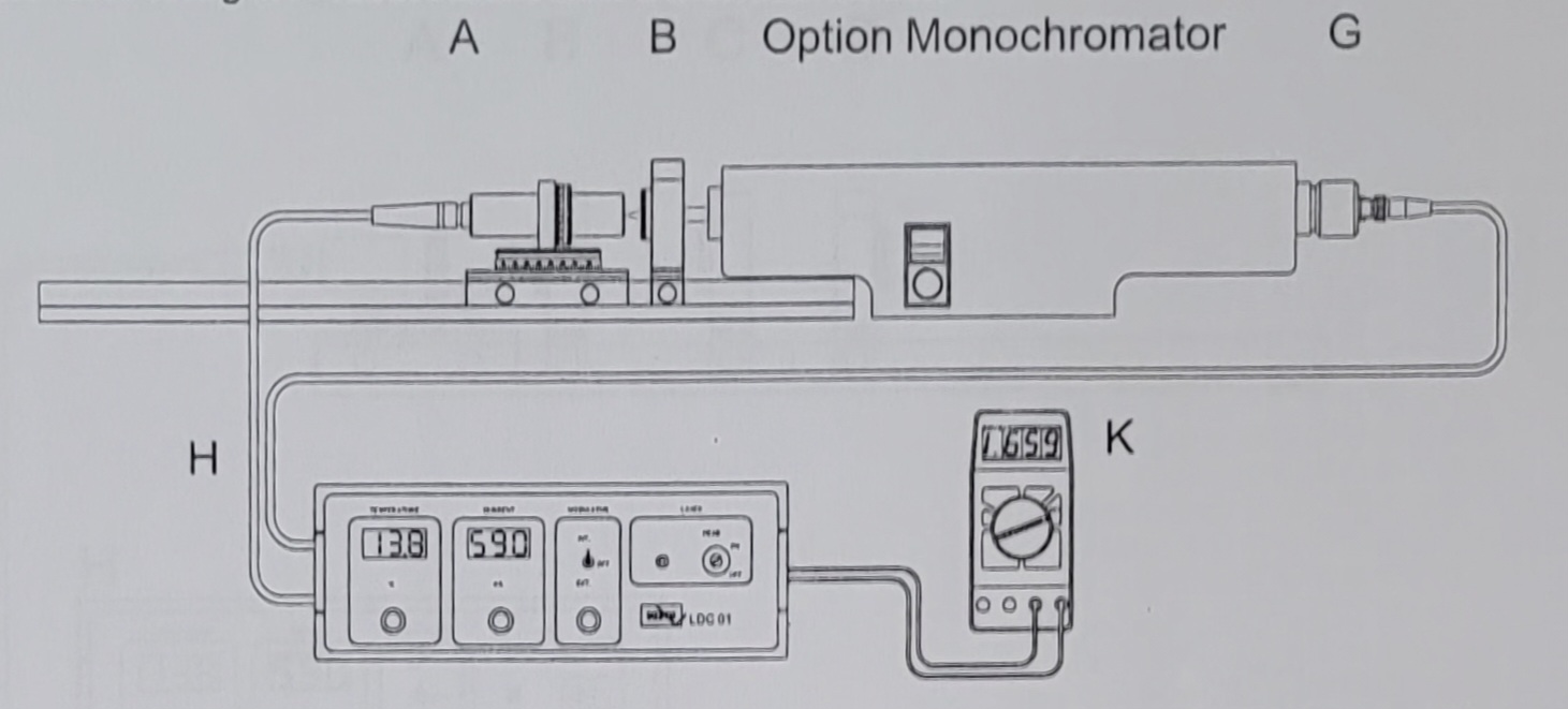
- Wavelength Dependence
- Wavelength Measurement With a Monochoromator
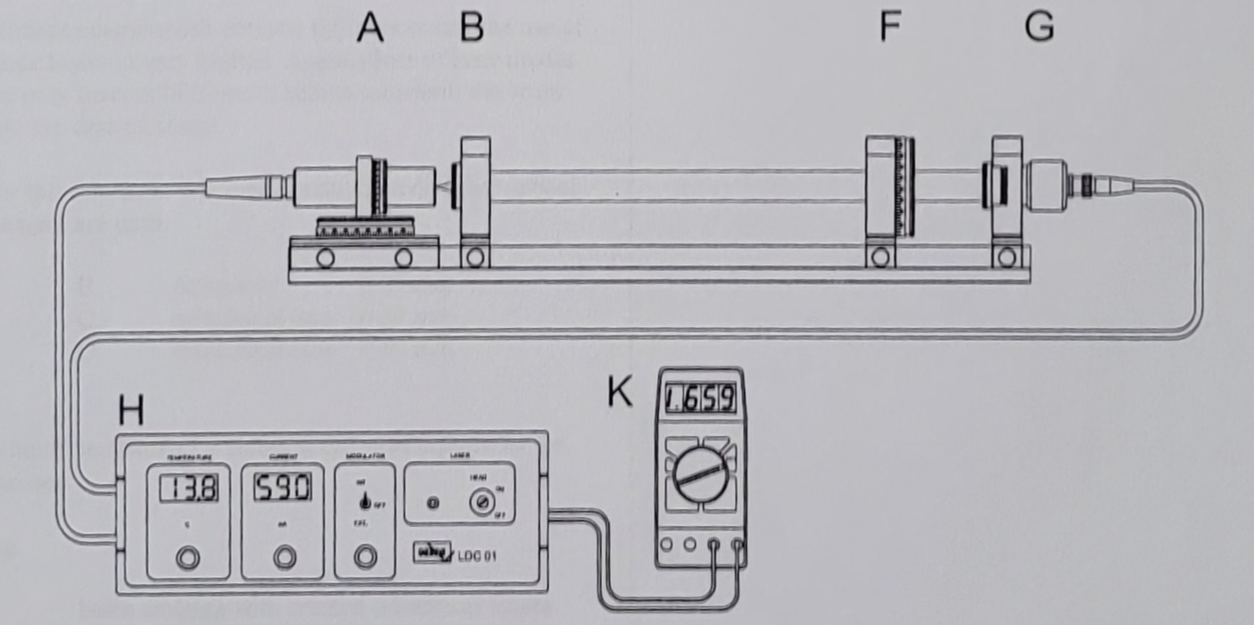
- Polarisation
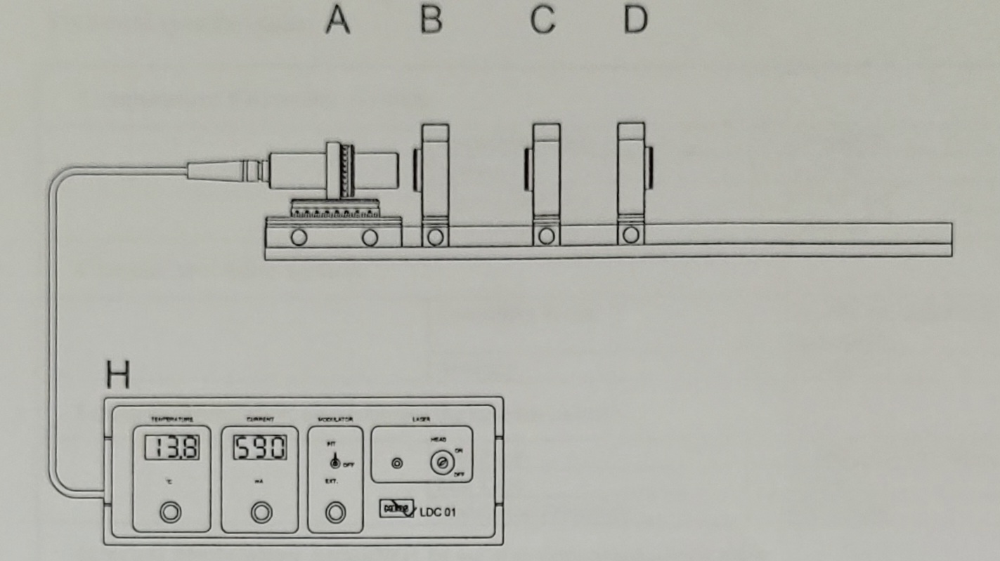
- Beam Shaping

Digital voltmeter - Module K
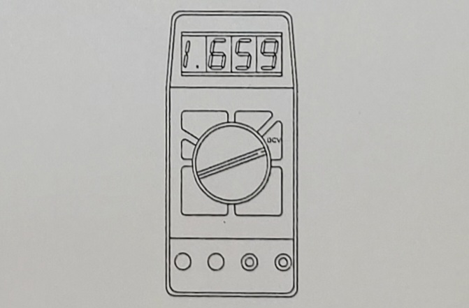
Digital voltmeter to be connected to the photo amplifier of controller LDC-01.
Цифровой вольтметр подключить к фотоусилителю контроллера LDC-01.
PIN - Photodiode d=1mm - Module G
Module G
A PIN-photodiode mounted in a housing with click mechanism and BNC-socket. By means of the attached BNC-cable the detector is connected to the amplifier of module H. A pinhole d=1mm is used as diaphragm.
PIN-фотодиод, установленный в корпусе с защелкивающимся механизмом и BNC-гнездом. С помощью прилагаемого BNC-кабеля детектор подключается к усилителю модуля H. В качестве диафрагмы используется отверстие d=1 мм.
Polarisation analyser mounted - Module F
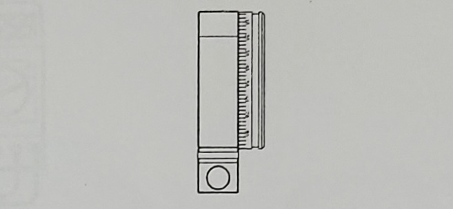
Polarisation analyser mounted on a mounting plate with rotational adjustment and carrier.
Анализатор поляризации смонтирован на монтажной плате с поворотной регулировкой и держателем.
Nd: YAG rod - Module E
Module E
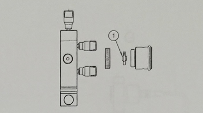
Nd:YAG rod mounted in adjustment holder as wavelength selective element.
Стержень Nd:YAG, установленный в регулировочном держателе в качестве элемента, селективного по длине волны.
Optics for beam shaping Cylindical lens F=80 mm - Module D
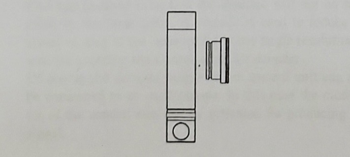
Optics for beam shaping consisting of a cylindrical lens with f=80 mm and a mounting plate on carrier.
Optics for beam shaping Cylindical lens F=20mm - Module C
Optics for beam shaping consisting of a cylindrical lens with f=20 mm and a mounting plate on carrier.
Оптика для формирования луча, состоящая из цилиндрической линзы с f=20 мм и монтажной пластины на держателе.
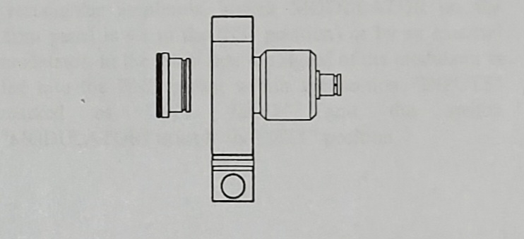
Collimation Optics for the diodelaser FL=20mm - Module B
Коллимационная оптика для диодного лазера, состоящая из ахроматического объектива с фокусным расстоянием 20 мм и монтажной пластины на носителе.
Diodelaser 30mW at 808nm - Modoule A
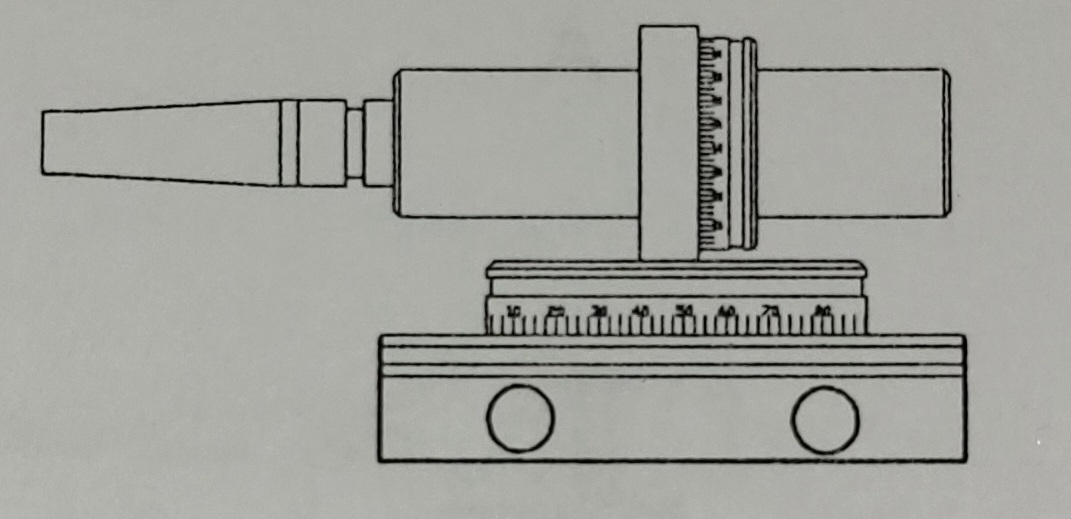
Module A
Didoelaser 30 mW at 808 nm with Peltier cooler and thermistor. The laser head is mounted in a mounting plate on carrier in a way that it can be rotated around the laser axis as well as vertical to the axis.
Дидолазер 30 мВт на длине волны 808 нм с охладителем Пельтье и термистором. Лазерная головка установлена на монтажной пластине на держателе таким образом, что ее можно вращать вокруг оси лазера, а также вертикально к оси.